No products
 View larger
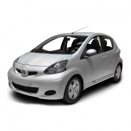
 Toyota Aygo (2005-2014) - Wiring and Electrical Circuits
English Wiring and Electrical Circuits for vehicles Toyota Aygo (2005-2014)
---- INSTANT DOWNLOAD ----
LANGUAGE: English.
FORMAT: PDF file
PAGES: 346
VALID FOR: Windows, Mac, Android and iOS.
PRINTABLE: Yes
Digital product, sent to email.
More info
TOYOTA AYGO (2005-2014) - WIRING DIAGRAMS - COMPONENTS LOCATOR
- English Electrical Wiring Diagrams and Components Locator for vehicles Toyota Aygo 2005 to 2014.
- MODELS CODE: KGB10,WNB10
- ENGINES CODE: 1KR-FE,2WZ-TV
CONTENTS:
ELECTRICAL WIRING DIAGRAMS
- ABS
- ABS , TRC , VSC
- Air Conditioner
- Audio System
- Back-Up Light
- Cooling Fan
- Cooling Fan
- Cooling Fan
- Combination Meter
- Charging
- Charging
- Door Lock Control
- DLC3
- Engine Control
- Engine Control
- Engine Immobiliser System
- EPS
- Front Fog Light
- Front Wiper and Washer
- Ground Point
- Headlight Beam Level Control
- Heater
- Headlight
- Headlight
- Horn
- Interior Light
- Illumination
- Ignition
- Light Reminder
- Multi-mode Manual Transmission
- Multiplex Communication System
- Power Outlet
- Power Source
- PTC Heater
- Power Window
- Rear Fog Light
- Rear Window Defogger
- Rear Wiper and Washer
- Seat Belt Warning
- Stop Light
- SRS
- Starting
- Taillight
- Tachometer
- Turn Signal and Hazard Warning Light
- Wireless Door Lock Control
OVERALL ELECTRICAL WIRING DIAGRAMS
- Power Source
- S ChargingIgnitiontarting
- Engine Control (1KR–FE)
- DLC3Engine Immobil iser System
- Headl ight (w/ Daytime Running Light) (Before Feb. 2012 Production)
- Headl ight (w/o Daytime Running Light)Interior LightHorn
- Taillight
- Headl ight Beam Level Control
- Stop LightBack–Up Light
- Rear Fog Light
- Turn Signal and Hazard Warning Light
- Illumination
- ABS (w/o VSC)
- SRS
- EPSSeat Bel t WarningLight Reminder
- Front Wiper and WasherRear Wiper and Washer
- Door Lock Control and Wirel ess Door Lock Control
- Power WindowRear Window Defogger
- Power Out l et Opt i on Connector Audio System
- Cool ing Fan (1KR–FE)Tachometer
- Combination Meter
- HeaterAir Conditioner
- Engine Control (2WZ–TV)
- Mul ti–mode Manual Transmission
- Cool ing Fan (2WZ–TV w/ Air Conditioner) Cool ing Fan (2WZ–TV w/o Air Conditioner) PTC Heater
- ABS (w/ VSC), TRC and VSC
- Mul tipl ex Communication System (CAN)
- Front Fog Light
- Headl ight (w/ Daytime Running Light) (From Feb. 2012 Production)
COMPONENTS LOCATIONS
- Position of Parts in Engine Compartment
- Wire and Wire , Ground Points in Engine Compartment
- Position of Parts in Engine Compartment
- Wire and Wire , Ground Points in Engine Compartment
- Position of Parts in Engine Compartment
- Wire and Wire , Ground Points in Engine Compartment
- Position of Parts in Engine Compartment
- Wire and Wire , Ground Points in Engine Compartment
- Position of Parts in Body
- Wire and Wire , Ground Points in Body
- Position of Parts in Body
- Wire and Wire , Ground Points in Body
- Position of Parts in Body
- Wire and Wire , Ground Points in Body
- Position of Parts in Body
- Wire and Wire , Ground Points in Body
- Ground Points in Instrument Panel
- Position of Parts in Instrument Panel
- Wire and Wire in Instrument Panel
- Ground Points in Instrument Panel
- Position of Parts in Instrument Panel
- Wire and Wire in Instrument Panel
RELAY LOCATIONS
- [Engine Compartment]
- [Center Connector Inner Circuit]
- [Engine Room R/B and Engine Room J/B Inner Circuit]
- [Instrument Panel J/B Inner Circuit]
- [Instrument Panel]


