No products
 View larger
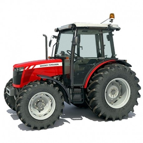
 Massey Ferguson Tractor MF 3600 Series - Workshop Manual / Repair Manual
English Workshop Manual / Repair Manual, to tractors Massey Ferguson Tractor MF 3600 Series.
--------- INSTANT DOWNLOAD ---------
LANGUAGE: English.
FORMAT: PDF file
PAGES: 763
VALID FOR: Windows, Mac, Android and iOS.
PRINTABLE: Yes
Digital product, sent to email.
More info
MASSEY FERGUSON MF3600 SERIES - WORKSHOP, SERVICE, REPAIR MANUAL
- English Workshop Manual / Repair Manual, to tractors Massey Ferguson Tractor MF 3600 Series.
INDEX:
INTRODUCTION
- Indexing
- Definition of Terms
- Special Tools
- Repairs and Replacements
- Repair of the Tractor
- Amendments
Safety Alert Symbol and Terms
SAFETY IN THE WORKSHOP
SAFETY - A WORD to the MECHANIC
SAFETY - DANGER, WARNING and CAUTION
SAFETY DECALS
GENERAL
PERSONAL CONSIDERATIONS
- Clothing
- Eye Protection
- Breathing Protection
- Hearing Protection
- Hand Protection
- Foot Protection
- Special Clothing
EQUIPMENT CONSIDERATIONS
- Machine Guards
- Lifting Appliances
- Jacking
- Compressed Air
- Hand Tools
- Electricity
GENERAL CONSIDERATIONS
- Solvents
- Housekeeping
- Fire
- First Aid
OPERATIONAL CONSIDERATIONS
SERVICING TECHNIQUES
- Service Safety
- Service Techniques
- Hoses and Tubes
- Bearings
- Shims
- Gaskets
- Lip Type Seals
- Use of Bolts in Blind Holes
- Locking Devices
- Cables and Wires
2 MF3600-MT300B.pdf
- Manual use
- Agreements and definitions
- General description
- Product identification
- General description
- Steering angle
- Steering radius
- Travel speed
- Tyre
- Battery
- Alternator
- Air filter
- Air filter line
- Battery
- Alternator
- Radiator
- Fan
- Exhaust pipe
- Fan belt
- Air filter assy replacement
- Bonnet
- Front weight
- Oil cooler
- Muffler
- Hydraulic pump
- Starting motor
- Engine removal
- Front axle 2WD
- Fuel tank
- Brake cylinder
- Hand brake adjustment
- Lock valve
- Rockshaft valve
- Rear wheels
- Auxiliary distributors
- Oil suction strainer
- Oil filter cartridge replacement
- Side auxiliary distributors
- Powershuttle hydraulic valve
- Oil filter sensor
- Clutch box
- Rockshaft
- Platform
- Steering valve
- Brake circuit bleeding
- Electric diagram
- Beacon light line
- NA right turn signal light line
- NA left turn signal light line
- Cab rear beam line
- Alternator cable
- Battery positive
- Battery negative
- Ground connector
- License plate light extension
- Beams extension
- Connector PTO 540 only
- NA cab front beam line
- Cab swinging beam extension
- Hydraulic system components
- Troubleshooting
- Axle problems and diagnosis
- SPECIFICATIONS
- diagram
- Circuit diagram of hydraulic lifting device
- Functioning of Control Valve
- HOW THE Internal Leverage System Functions
- use of control Levers
- adjustment of Control Valve Sensitivity
- ADJUSTMENT OF POSITION CONTROL LEVER
- ADJUSTMENT OF DRAFT CONTROL LEVER
- CONTROL OF ASSEMBLY OF REACTION SPRING
- MEASUREMENT CONTROL OF PUSH ROD
- DIAGNOSTIC
3 Procedures.pdf
- Disassembly
- Assembly
4B CA357471.pdf
- Intended use
- Product identification
- Technical features
- Tightening torques, sealants and grease application
- Hi/LO Power flows
- Assembly typical data
- Filling and checks
- Service schedule
- Hydraulic system assy
- Drop box
- Final drive - from 55 to 75 HP
- Final drive - 85 HP
- Teflon seals replacement (clutch shaft)
- Input shaft and support
- Upper covers and rockshaft
- Speed and ranges levers
- Clutch housing - synchro shuttle
- Clutch Housing - Synchro splitter
- Synchro shuttle and Power splitter
- Power shuttle - Power shuttle and Synchro splitter
- Air compressor
- Wet clutch - Power splitter
- Wet clutch - Power shuttle
- Hi-LO synchronizer (synchro splitter)
- Cover and PTO wet clutch
- PTO - Power take off
- PTO Input shaft
- PTO Output shaft
- PTO Brake
- Ground Drive PTO
- Slave cylinder
- Parking brake
- Housing sensors assy
- Differential locking control
- Inner control assy
- Idle gear
- Power shuttle
- Range gears (primary shaft)
- Input shaft - synchro shuttle
- Input shaft - 12+12 power shuttle
- Synchronizer shuttle (replacement)
- Speed gears (PRIMARY SHAFT)
- Differential assy
- Pinion - Ranges Pinion - Ranges (SECONDARY SHAFT)
- secondary shaft
- Speed gears (secondary shaft)
- Special tools
5A CA357465.pdf
- Manual use
- Information property
- Agreements and definitions
- General description
- Recommendations for repair operations
- Intended use
- Product identification
- General description
- Technical Features
- Maintenance
- Grease in assembly
- Adhesive and sealant
- Tightening torques
- Steering cylinder group
- Wheel hub group
- Wheel hub support group
- Axle beam group
- Toe-in/steering angle
- Troubleshooting
- Axle problem and diagnosis
- Special tools
- Service operations time schedule
5B CA357464.pdf
- Manual use
- Information property
- Agreements and definitions
- General description
- Recommendations for repair operations
- Intended use
- Product identification
- General description
- Technical Features
- Maintenance and oil change
- Grease in assembly
- Adhesive and sealant
- Tightening torques
- Steering cylinder group
- Epicyclic reduction gear group
- Wheel hub group
- Axle beam group
- Trunnions group
- Differential support group
- Differential group
- Pinion group
- Toe-in/steering angle
- Testing after assembly
- Troubleshooting
- Axle problem and diagnosis
- Special tools
- Service operations time schedule


