No products
 View larger
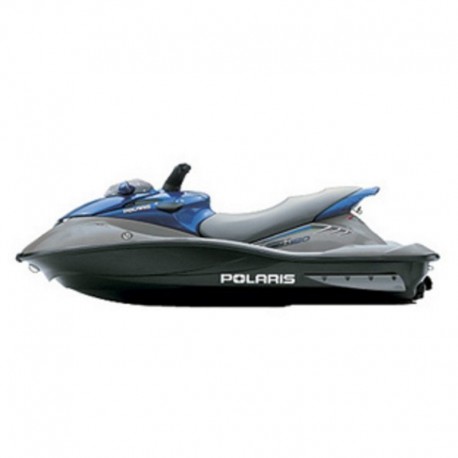
 Polaris MSX 150 - Workshop Manual and Parts Manual
English Workshop Manual and Parts Manual, to Jet Ski Polaris MSX 150.
--------- INSTANT DOWNLOAD ---------
LANGUAGE: English.
FORMAT: PDF file
PAGES: 299
VALID FOR: Windows, Mac, Android and iOS.
PRINTABLE: Yes
Digital product, sent to email.
More info
POLARIS MSX 150 - SERVICE MANUAL & PARTS MANUAL
- English Workshop Manual and Parts Manual, to Jet Ski Polaris MSX 150.
INDEX:
Workshop Manual
table of contents
- chapter 1-general information
-- service guidelines/safety warnings
-- msx 150 general information
-- msx 150 general information
-- standard torque specifications
-- conversion chart
-- tap drill sizes
-- service tools
- chapter 2-maintenance
-- periodic maintenance table
-- safety warnings
-- flush kit
-- service products
-- steering/reverse system lubrication
-- steering/post removal/assembly
-- steering/reverse cable adjustment
-- e.s.p. function testing
-- valve clearance adjustment procedure
-- engine oil level check
-- oil change procedure
-- engine coolant inspection/change procedure
-- cooling system pressure test
-- engine compression/fuel system pressure tests
-- battery safety and maintenance
-- spark plug
-- fuses
-- exhaust cooling injector maintenance
-- throttle cable adjustment
-- gasoline safety/fuel system maintenance/fuel filter
-- bilge system/siphons
-- propulsion system maintenance
-- hndlebar maintenance/intake manifold re-torque procedure
-- drain plugs
-- off-season storage
- chapter 3-engine removal/installation
-- engine subassembly removal
-- engine mount removal
-- engine installation
- chapter 4-engine disassembly/assembly
-- engine specifications
-- engine fastener torque specifications
-- service tools
-- oil filter assembly
-- valve cover assembly
-- dry sump oil pump assembly
-- thermostat housing
-- high pressure oil pump assembly
-- chain guide and chain tensioner assembly
-- engine case/cylinder head assembly
-- piston assembly
-- vavle assembly
-- balance plate/pto assembly
-- crankshaft/balance shaft assembly
-- engine disassembly
-- engine assembly
-- timing chain installation/timing procedure
-- freshwater/internal engine cooling systems
-- thermostat, water pump & seal removal/installation
-- freshwater cooling circuit illustrations
-- oil lubrication system
-- crankcase ventilation system
-- oil pump(s) removal and installation
-- oil lubrication illustrations
- chapter 5-fuel injection/ignition/exhaust systems
-- bosch engine management system overview
-- engine management system specifications
-- air inlet hose routings
-- fuel hose routings
-- vent hose routing
-- fuel tank assembly illustration
-- fuel supply/vent hose illustration
-- fuel rail/injector illustration
-- electronic throttle body illustrations
-- spark plug/ignition coil illustration
-- ecu mounting illustration
-- ecu wiring harness connector illustrations
-- engine management sensor circuit drawings w/trouble codes
-- ecu connectors
-- ecu trouble codes
-- electronic throttle body/ppu troubleshooting
-- exhaust system illustration
-- turbocharger/wastegate overview
-- charge air cooler overview/turbocharger troubleshooting
-- rpm limiting modes
-- troubleshooting: engine will not turnover
-- troubleshooting: engine turns over; will not start
-- troubleshooting: engine stalls; will re-start
-- troubleshooting: engine stalls: will not re-start
-- troubleshooting: engine lacks performance, rpm limits
-- troubleshooting: general
- chapter 6-propulsion
-- ventilation/cavitation troubleshooting
-- pump assembly illustration
-- stator assembly illustration
-- driveshaft assembly illustration
-- pump induction assembly illustration
-- pump removal and assembly
-- bearing carrier removal and installation
-- driveshaft shim procedure
-- driveline inspections
-- stator disassembly ans assembly
-- driveshaft alignment procedure
-- sacrificial anode
-- intake scoop/ride plate removal and installation
- chapter 7-hull and body
-- hull specifications/paint codes
-- fastener guide
-- steering/reverse cable routing
-- siphon hose routing
-- hull assembly illustration
-- compartment door assembly
-- shroud and storage assemblies
-- seat assembly
-- steering control assembly
-- ppu assembly
-- reverse system assembly
-- handlebar/ steering post removal
-- steering cable removal and installation
-- steering/reverse cable adjustment
-- top deck/hull repair
- chapter 8-electrical systems
-- chassis electrical and sensor specifications
-- battery and charging system specifications
-- ngi gauge
-- ngi gauge wiring illustration/mil indicators
-- battery testing/maintenance
-- alternator assembly
-- charging system illustration
-- start/stop electrical system illustration
-- system interface box overview
-- starter motor illustration
-- starter motor disassembly/assembly/troubleshooting
- wiring diagrams
- index
-- a-e
-- f-p
-- r-w
Parts Manual
- a
- airbox d1
- b
- battery box . b6
- c
- chain tensioner . c5
- compartment door a3
- coolant bottle . d7
- coolant elbow d8
- coolant rail b10
- cooling system . b4
- crankshaft and balance shaft b12
- cylinder c7
- d
- decals . b8
- drive system a12
- e
- ecu mounting . d14
- electrical b5
- engine bedplate . d2
- engine mounting b7
- enhanced steering performance . d12
- exhaust gaskets and hardware . c10
- exhaust system . b3
- f
- flywheel . c2
- fuel rail c9
- fuel system . a9
- fuel tank . a8
- h
- heat exchanger . d5
- hull and body . a5-6
- i
- ignition coils . c11
- intake d4
- intercooler d3
- m
- magneto c1
- o
- oil cooler c14
- oil filter . c6
- oil lines d6
- oil pump b14
- oil sump b9
- oil tank . d6
- p
- piston and rod . b13
- popoff valve d1
- ppu asm. d13
- propulsion . a14
- r
- reverse a13
- s
- seat a7
- sensors d10
- shroud and storage . a4
- steering a10
- steering cable a11
- t
- throttle body d4
- tool kit . d11
- turbocharger and lines c12-13
- v
- valve cover . c8
- valve train c4
- valves c3
- voltage regulator d9
- w
- water exchanger . d5
- water inlet . b1
- water pump . b11
- water siphon . b2


