No products
 View larger
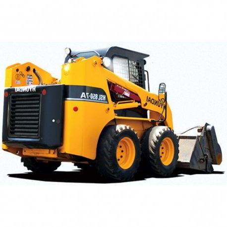
 Hyundai Skid Steer Loader HSL850-7A - Workshop Manual - Operators Manual - Wiring Schematics
English Workshop Manual, Operators Manualand Wiring Schematics, for Skid Steer Loader Hyundai HSL850-7A.
--------- INSTANT DOWNLOAD ---------
LANGUAGE: English.
FORMAT: PDF file
PAGES: 454
VALID FOR: Windows, Mac, Android and iOS.
PRINTABLE: Yes
Digital product, sent to email.
More info
HYUNDAI HSL850-7A - WORKSHOP, SERVICE, REPAIR MANUAL - OPERATORS MANUAL - WIRING SCHEMATICS
- English Workshop Manual, Operators Manual and Wiring Schematics, for Skid Steer Loader Hyundai HSL850-7A.
INDEX:
SERVICE MANUAL
- SECTION 1
- GENERAL
- Group 1 Safety Hints
- Group 2 Specifications
- Group 3 Maintenance
- SECTION 2
- HYDRAULIC SYSTEMUNCTION
- Group 1 Hydraulic circuit
- Group 2 Hydraulic component testing
- Group 3 Self level valve(Option)
- Group 4 Auxiliary pump
- Group 5 Main pump
- Group 6 Travel motor
- Group 7 Main control valve
- Group 8 Boom and bucket cylinder
- SECTION 3
- ELECTRICAL SYSTEM
- Group 1 Component location
- Group 2 Wiring diagram
- Group 3 Electrical component specification
- Group 4 Connector destination
- SECTION 4
- POWER TRAIN
- Group 1 Power train component
- Group 2 Front and rear axle
- SECTION 5
- CONTROL
- Group 1 Hand control
- Group 2 Parking brake
- Group 3 Attachment holder
- SECTION 6
- TROUBLE SHOOTING
- Group 1 Travel hydraulics
- Group 2 Boom and bucket hydraulic
- Group 3 Power train
- Group 4 Control
- Group 5 Electrical system
ENGINE SERVICE MANUAL
GENERAL
- 1 Engine Identification G-1
- [1] Model Name And Engine Serial Number G-1
- [2] E2b Engine G-3
- [3] Cylinder Number G-3
- 2 General Precautions G-4
- 3 Maintenance Check List G-5
- 4 Check And Maintenance G-7
- [1] Daily Check Points G-7
- [2] Check Points Of Initial 50 Hours G-9
- [3] Check Point Of Every 50 Hours G-11
- [4] Check Points Of Every 250 Hours G-12
- [5] Check Points Of Every 500 Hours G-14
- [6] Check Point Of Every 1000 Hours G-17
- [7] Check Points Of Every 1 Or 2 Months G-18
- [8] Check Points Of Every 1500 Hours G-20
- [9] Check Points Of Every 3000 Hours G-21
- [10]Check Points Of Every 1 Year G-24
- [11]Check Points Of Every 2 Years G-25
- 5 Special Tools G-28
MECHANISM
- 1 Feature M-1
- 2 Engine Body M-2
- [1] Cylinder Block M-2
- [2] Cooling Jacket M-3
- [3] Half-Floating Head Cover M-3
- [4] Cylinder Head M-4
- [5] 4 Screws Per Each Cylinder Assembling Structure M-5
- [6] Center Direct Injection System (E-Cdis) M-6
- [7] Gear Train Configuration M-7
- [8] Piston M-7
- [9] Built-In Dynamic Balancer (Balancer Model Only) M-7
- 3 Lubricating System M-8
- [1] Oil Cooler M-8
- 4 Cooling System M-9
- [1] Thermostat M-9
- [2] Bottom Bypass System M-10
- 5 Fuel System M-11
- [1] Governor M-11
- [2] 2 Stage Di Nozzle M-14
- [3] Injection Pump With Fsp M-15
- [4] Cpv Equipped Delivery Valve M-16
- 6 Intake And Exhaust System M-17
- [1] Turbocharger M-17
SERVICING
- 1 Troubleshooting S-1
- 2 Servicing Specifications S-5
- 3 Tightening Torques S-12
- [1] Tightening Torques For General Use Screws, Bolts
- And Nutss-12
- [2] Tightening Torques For Special Use Screws, Bolts
- And Nutss-13
- 4 Checking, Disassembling And Servicings-15
- [1] Checking And Adjustings-15
- Engine Bodys-15
- (2) Lubricating System S-17
- (3) Cooling Systems-17
- (4) Fuel System S-20
- (5) Electrical System S-23
- (6) Turbocharger S-27
- [2] Disassembling And Assemblings-28
- Draining Oil And Coolants-28
- (2) External Components S-28
- (3) Cylinder Head And Valves S-31
- (4) Thermostats-35
- (5) Injection Pump Units-36
- (6) Water Pump And Oil Cooler S-45
- (7) Front Cover S-46
- (8) Flywheel And Timing Gears S-47
- (9) Piston And Connecting Rod S-51
- (10)Crankshaft And Crankcase S-54
- (11)Starter S-56
- (12)Alternator S-56
- [3] Servicing S-59
- Cylinder Head And Valves S-59
- (2) Timing Gears S-65
- (3) Piston And Connecting Rod S-67
- (4) Crankshafts-70
- (5) Cylinders-74
- (6) Oil Pump S-75
- (7) Relief Valves-76
- (8) Starter S-76
- (9) Alternator S-78
OPERATORS MANUAL
- Foreword
- Section 1
- Safety hints
- Section 2
- Specifications
- Section 3
- Control devices
- Section 4
- Operation
- Section 5
- Transportation
- Section 6
- Maintenance
- Section 7
- Troubleshooting


