No products
 View larger
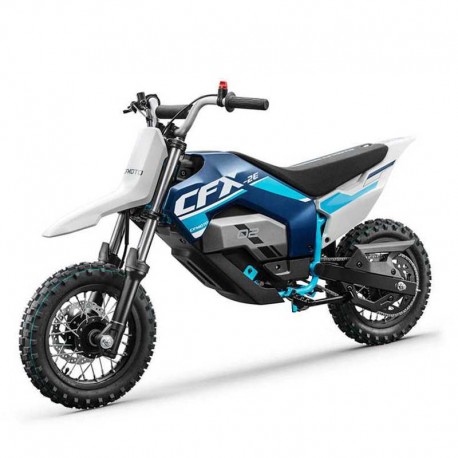
 Cfmoto CFX-2E CFX-5E (2023-2024) - Workshop Repair Manual - Maintenance
English Workshop and Maintenance Manual for motorcycles Cfmoto CFX-2E CFX-5E (2023-2024)
---- INSTANT DOWNLOAD ----
LANGUAGE: English.
FORMAT: PDF file
PAGES: 164
VALID FOR: Windows, Mac, Android and iOS.
PRINTABLE: Yes
Digital product, sent to email.
More info
CFMOTO CFX-2E CFX-5E (2023-2024) - SERVICE MANUAL - REPAIR MANUAL
- English Service Manual / Repair Manual for motorcycles Cfmoto CFX-2E CFX-5E 2023 to 2024.
- Edition Item:CF650DY(ED20-00WX01-0000)SM-20230731 / CF1000DY-2/CF2000DY(EC31-00WX01-0000) SM -20241118
CONTENTS:
1 SERVICE INFORMATION
- 1.1 General Precautions
- 1.2 Repair Precautions
- 1.3 Number Engrave Place
2 MAINTENNANCE INFORMATION
- 2.1 Daily Maintenance Schedule
- 2.1.1 Pre-Ride Maintenance Checklist
- 2.2 Maintenance Schedule During Break-in Period
- 2.3 Periodic Maintenance Schedule
3 TECHNICAL INFORMATION
- 3.1 General Specification
- 3.2 Motor and Controller Parameters
- 3.3 Battey Specification
- 3.4 Maintenance Specifications
- 3.4.1 Front Wheel
- 3.4.2 Rear Wheel
- 3.4.3 Shock Absorber
- 3.4.4 Brake System
- 3.4.5 Dashboard and Switches
- 3.5 Tighten Torque
- 3.5.1 Tighten Torque Table for Normal Parts
- 3.5.2 Tighten Torque Table for Key Parts
- 3.6 Lubrication
04 SEAT
- 4.1 Seat Removal
- 4.2 Seat Installation
05 BODY PLASTIC PARTS
- 5.1 Front Fender Assembly
- 5.2 Front Fender Assembly
- 5.2.1 Disassemble the Front Fender Assembly
- 5.3 Central Panel
- 5.3.1 Disassemble the Central Panel
- 5.4 Central Panel
- 5.4.1 Disassemble the Central Panel
- 5.5 Disassemble the Lower Panel
- 5.6 Disassemble the Lower Panel
- 5.7 Disassemble the Side Panel
- 5.8 Disassemble the Rear Fender
- 5.8.1 Disassemble the Rear Fender
- 5.9 Disassemble the Rear Fender
- 5.9.1 Disassemble the Rear Fender
- 5.10 Chain Guard
6 ELECTRICAL SYSTEM
- 6.1 Service Information
- 6.1.1 Operation Notice
- 6.2 Notice Before Service
- 6.3 Electrical Throttle
- 6.4 Integrated Motor
- 6.4.2 Motor Controller
- 6.4.1 E-control Connector Function
- 6.5 Motor
- 6.5.1 MCU
- 6.5.2 MCU Pin Function
- 6.6 DC-DC Converter
- 6.7 Dashboard
- 6.7.1 Pin Function
- 6.7.2 Pin Function
- 6.8 Fault Code for Vehicle
- 6.9 Fault Code for Vehicle
- 6.9.1 BMS
- 6.9.2 MCU
7 WHEELS AND BRAKE SYSTEM
- 7.1 Front Hydraulic Brake Assembly
- 7.2 Front Wheel
- 7.2.1 Front Brake Disc
- 7.3 Rear Wheel
- 7.3.1 Sprocket Disc
- 7.3.2 Rear Brake Disc
- 7.4 Rear Hydraulic Brake
- 7.5 Tire Inspection
- 7.5.1 Tire Pressure
- 7.5.2 Tire Apperance
- 7.5.3 Wheel Bearing
- 7.5.4 Brake Disc Inspection
- 7.6 Brake System Maintenance
- 7.6.1 Front Brake Main Cylinder Maintenance
- 7.6.2 Front Brake Main Cylinder Maintenance
- 7.6.3 Rear Brake Master Cylinder Maintenance
- 7.6.4 Brake Hose Maintenance
- 7.6.5 Brake Caliper Assembly and Brake Disc Maintenance
08 POWER ASSEMBLY
- 8.1 Battery
- 8.2 Battery
- 8.3 Drive Sprocket
- 8.4 Drive Sprocket
- 8.5 Motor Assembly
- 8.6 Motor Assembly
09 SHOCK ABSORBER, REAR FORK ASSEMBLY
- 9.1 Front Bracket (Front Fork) Assembly Diagram
- 9.2 Front Bracket (Front Fork) Assembly Diagram
- 9.3 Front Shock Absorber
- 9.4 Rear Shock Absorber
- 9.5 Rear Fork
- 9.5.1 Chain Slider Removal
- 9.6 Chain
- 9.7 Chain
- 9.8 Drive Chain Tightness Adjustment
- 9.9 Front Shock Absorber Inspection
- 9.10 Rear Shock Absorber Inspection
- 9.11 Rear Shock Absorber Adjustment
10 HANDLEBAR, TRIPLE CLAMP ASSEMBLY
- 10.1 Emergency Stop Switch
- 10.2 LH Handlebar, Electrical Throttle Assembly
- 10.3 Handlebar, Triple Clamp Assembly Diagram
- 10.4 Handlebar, Triple Clamp Assembly Diagram
- 10.5 Handlebar Pipe
- 10.6 Upper Triple Clamp
- 10.7 Front Fork, Lower Triple Clamp Assembly


